THEORY OF EXTRUSION
To understand the effects occuring during the 3D print it is helpful to be familiar with the theory of the FDM. One may say, that is quite easy: we put a filament in to a nozzle, make it hot and use the extruded string for layer wise building of the programmed part.
Correct. Now we are facing the slicer software and have to set a lot of parameters. Therefore: start with the basics.
For the K8400 as well as the most other printers in the private usage we are taking plastic based filament for printing, where we have in general three important temperatures:
the glassification point: the temperature, when the filament becomes greasy/ductile
the liquidus point: the temperature. at which the solid filament becomes liquid
the decomposition point: the temperature, at which a chemical modification of the base plastics will appear.
All three temperatures have increasing values from the first to last point, for the two first points the supplier often provides values, the third one is rarely given. Instead a temperature range for the extrusion is often given, which is between the liquidus and decomposition point. Unfortunately no further information is given about the way how these values are generated, so they can be treated as first estimation for your own trials only.
When operating in the proposed temperature region, the filament becomes liquid. The important parameter for us is fluidity or viscosity of the material. These parameters are a measure how easy the material will flow. The lower the viscousity, the more "liquid" the material is. The viscousity is temperature dependent, most of the models have the temperature in the exponent, so a small variation in temperature will have a large impact on the viscousity. The most common model is the exponential model, which can be applied without large errors to our extrusion condition:
µ(T) = µ0 exp (-bT)
with µ0 and b material specific constants. This implies, that even small variation of the temperature can generate massive variations of the viscosity, only damped be the empirical factor b, which is never given.
Now we have liquid plastics and need to push them through the nozzle. This physical effect is covered by the Navier-Stokes equation, which is the physical "swiss knife" for most of the fluid dynamics. A special condition, the fluid flow through a round pipe, is presented as Hagen-Poiseuille equation, which can be written like that:
dP = 8µLQ / πr⁴
with dP the pressure drop across the nozzle
L the length of the nozzle channel
Q the volumetric flow rate
r the radius of the nozzle.
This equation contains several well known relationships, which will be resumed in a flash:
- to get a flow through the nozzle you have to apply a pressure.
- with the geometrical design of the nozzle (channel length, diameter) you can change the flow. small variations in the nozzle diameter are more effective than changing the channel lenght. With larger nozzle diameter we get a better flow (but reduced print resolution).
- at constant pressure the factor of viscosity and flow rate is constant. A higher viscosity will reduce the flow rate. Having in mind the temperature influence of the viscosity, we have now the same temperature sensity of the flow rate.
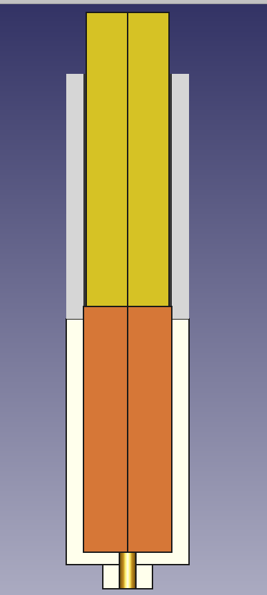
Now we have the liquid filament before the nozzle and have to apply the neccessary pressure to print the filament. The next graph depicts the actual situation in our printer: in the lower upper part of the nozzle we have the filament completely molten (orange). on top there is the filament guide with the solid filament (yellow). We have to apply some pressure to put the liquid through the small opening of the lower part of the nozzle.
How should we do this? The standard answer is: by pushing the filament. But would that work? Looking at the sketch above you may notice, that there is a gap between the inner diameter of the filament guide and the filament itself. Pushing the filament down will have the same effect like dumping a stamp into a glass of water: it will rise the fluid level, but hardly will pressurize the liquid.
We have to apply a seal to prevent the liquid filament to flow upwards along the gap. This is a tricky mechanism and combines of two effects, which work in the same direction.
For the first mechanism we let the liquid filament rise into the filament guide, filling the whole gap between the guide (PTFE tube) and the filament. Since this area is no linger heated, the liquid filament will cool down, heating up the PTFE tube and the filament. The higher the liquid will raise, the cooler it will become and finally becomes solid again. This solid part is filling the complete gap between guide and filament, forming the neccessary seal for the extrusion. Now, with moving the filament down, we can build up a pressure which will push the liquid filament through the nozzle.
The second effect will strengthen the seal. During the cooldown of the liquid filament the solid filament was heated up. For most of the commonly used filaments the temperature for the solidification is around 150°C, much higher than the glassification temperature. This means, that in that area the filament is not really solid but ductile. that means, that the force, which is applied to build up the pressure, will do some deformation of the filament too. The only way for deformation is the upsetting of the filament, which will take place until the whole diameter of the filament guide is filled up . So the lenght of the seal is increasing, ensuring a proper pressure generation and a flow through the nozzle.
We have seen, that the flow rate through the nozzle is directly proportional to the applied pressure, so with increasing pressure we will get more material out of the nozzle. Technically we are doing a slightly different thing: we are pushing the filament with a predefined speed through the nozzle. That means, that we have a predefined flow rate throught the nozzle, and by the equation given above, we have a resulting pressure. This pressure can be expressed by the force acting on the seal diameter. so with increasing extrusion speed the neccessary force to push the filament is increasing.
We have seen too, that with increasing pressure the length of the seal is growing. Unfortunately there is a physical effect called sliding friction. Due to this sliding friction the force needed to push the seal within the filament guide is increasing with increasing seal length. both forces together have to be provided by the extruder motor, the maximum extrusion speed is defined by the grip of the extruder, the maximum force it can apply on the filament.
Finally we have build up the seal and can start with real printing, where we are pushing the filament with constant velocity.
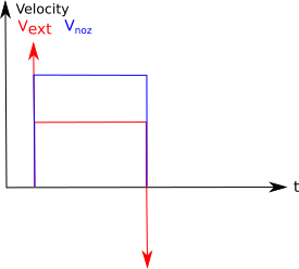
Having velocity Vext from the extruder shift, we will have a higher velocity Vnoz in the nozzle. Since no material will get lost, the material flow before and after the nozzle is the same. This can be expressed as
Vseal * Afil = Vnoz * Anoz. = Q
the relation between these two values is given by the ration of the nozzle diameter and fialment diameter.
Replacing the constant geometrical factors by a constant, the equation becomes
P = const * µ * Vseal*Afil
When we assume a negligible pressure of the filament outside the nozzle, the pressure drop across the nozzle becomes the absolute pressure P, which has to be applied by the pushing force of the extruder.
If we apply a force on a material, we will change the dimension of this material. This effect is generally known as deformation, which can be elastic (size will be recovered) or inelastic (material will remain in the changed size).
For the creation of the seal we need the inelastic deformation, for the building up of the pressure we have to apply an elastic deformation. This elastic deformation can be written as
dl = F/Afil * l/E
with dl the change of the filament length
l the filament length
E The elasticity number or Young*s modulus.
The Young's modulus is the material specific material constant which gives the relation between force and deformation. This constant can be found in various tables for room temperature.
for the 3D print we are working at significantly higher temperatures, and there will be a temperature gradient along the filament between the cold side and the hotend. Within this gradient the young's modulus will change dramatically. the following graph is giving an impression about this mechanism.
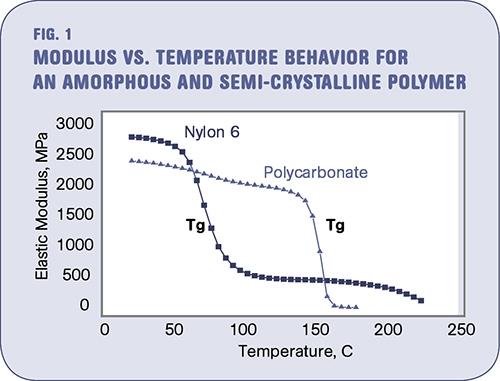
ref: http://www.ptonline.com/columns/the-effects-of-temperature
The transition point between the high elastic modulus and the low elastic modulus is at the glassification temperature, significantly below the melting point. So for the elastic deformation we have to split the above equation into a part with high elastic modulus at room temperature ERT and a part with a temperature above the glassification point Ehot. So the equation becomes
dlRT = F/Afil * lRT/ERT
dlhot = F/Afil* lhot/Ehot
dltotal = dlRT + dlhot = F/Afil (lRT/ERT + lhot/Ehot)
For the hot values of the Young's modulus there are no values available. However, from the experience I got in the meantime I can state, that the term for the room temperature is negligible for the most materials. Just for some special materials like elastic filament this part has to be respected too.
So when we push the filament through the nozzle a part of the movement is used to build up the pressure by elastic deformation. When we start the extrusion, the pressure is zero as well as the force. Without material flow through the nozzle this movement will generate a mechanichal stuffing of the hot filament. For a constant velocity this can be given as
dl = V * t
or in a generalised form
dl = ∫ V dt
When the first movement is done, a pressure is build up and the seal is moving in the same direction, reducing the presure generation. This can be written as
dl = ∫ (Vext - Vseal) dt
The force in the system must be the same at every point of the nozzle, so we can rewrite the equations like this:
dlhot = F/Afil* lhot/Ehot = ∫ (Vext - Vseal) dt
becomes for the solid part
F = Afil * Ehot/ lhot * ∫ (Vext - Vseal) dt
while the liquid part is
P = F/Afil = const * µ * Vseal*Afil
and becomes
F = const * µ * Vseal*Afil2
and finally
Afil * Ehot/
lhot * ∫ (Vext - Vseal) dt = const * µ *
Vseal*Afil2
We can remove one area and replace the Vseal with the velocity in the nozzle:
Ehot/ lhot * ∫ (Vext - Afil/Anoz*Vnoz) dt = const * µ * Vnoz*Anoz
Finally we have an equation showing the main parameters which contribute to the extrusion mechanism, but since the velocity in the nozzle is part of both sides of this equation and within the integral on the left side, there is linear function, which can describe the relationship between the velocity of the filament and the velocity of material in the nozzle.
When we remove the integral by differentiation of both sides of the equation, we will get the following equation
Vext - Afil/Anoz*Vnoz = (const * µ* Anoz * lhot/Ehot) * dVnoz/dt
which is the common description of a low pass filter with the term in the bracket as time constant. With this result we can continue to describe our extrusion system using the methods of the system theory.
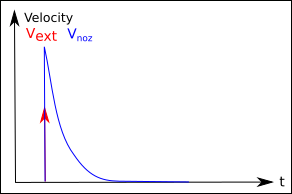
Within the system theory here are two very important reviews of a system:
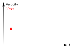
the response on a step function and the response on a Dirac delta
function.
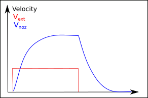
The first is given in the graphs below. The start of the extrusion is
done by switching on the extruder motor, which is pushing the filament
with a constant rate. This is represented as a step function for the
input.
The system is responding with an output function, where the velocity in
the nozzle is constantly increasing until the maximum value is achieved.
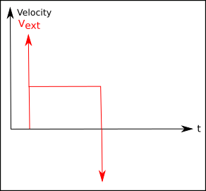
For switching off this delay is found in the other way round. This
behaviour can be expressed for nearly ideal systems by an exponential
curve. We can observe this effect too when extruding with the nozzle
lifted from the building plate.
 ->
-> 
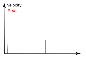
So what is the consequence of this behaviour:
1) we will not get good parts since at the beginning of the extrusion too
few material will be provided for printing
2) After the filament pushing stops, there will be still material run
through the nozzle, it is "dripping".
 ->
-> 
 ->
->